- 您现在的位置:买卖IC网 > Sheet目录3854 > PIC18F4450-I/PT (Microchip Technology)IC PIC MCU FLASH 8KX16 44TQFP
153
XMEGA A [MANUAL]
8077I–AVR–11/2012
14.3
Block Diagram
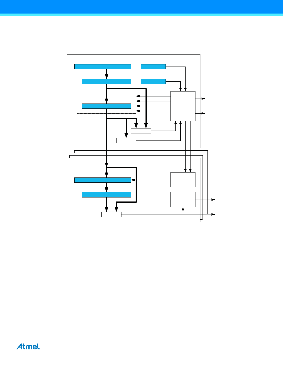
Figure 14-2 on page 153 shows a detailed block diagram of the timer/counter without the extensions.
Figure 14-2. Timer/counter block diagram.
The counter register (CNT), period registers with buffer (PER and PERBUF), and compare and capture registers with
buffers (CCx and CCxBUF) are 16-bit registers. All buffer register have a buffer valid (BV) flag that indicates when the
buffer contains a new value.
During normal operation, the counter value is continuously compared to zero and the period (PER) value to determine
whether the counter has reached TOP or BOTTOM.
The counter value is also compared to the CCx registers. These comparisons can be used to generate interrupt
requests, request DMA transactions or generate events for the event system. The waveform generator modes use these
comparisons to set the waveform period or pulse width.
A prescaled peripheral clock and events from the event system can be used to control the counter. The event system is
also used as a source to the input capture. Combined with the quadrature decoding functionality in the event system
(QDEC), the timer/counter can be used for quadrature decoding.
14.4
Clock and Event Sources
The timer/counter can be clocked from the peripheral clock (clkPER) or the event system, and Figure 14-3 shows the
clock and event selection.
Base Counter
Compare/Capture
(Unit x = {A,B,C,D})
Counter
=
CCx
CCBUFx
Waveform
Generation
BV
=
PERBUF
PER
CNT
BV
= 0
"count"
"clear"
"direction"
"load"
Control Logic
CTRLD
CTRLA
OVF/UNF
(INT/DMA Req.)
ERRIF
(INT Req.)
TOP
"match"
CCxIF
(INT/DMA
Req.)
Control Logic
Clock Select
"e
v"
UP
DA
TE
BOTTOM
OCx Out
Event
Select
发布紧急采购,3分钟左右您将得到回复。
相关PDF资料
21FMN-BMTTR-A-TB
CONN FMN HSNG 21POS STAG REV SMD
PIC16LF87-I/ML
IC MCU FLASH 4KX14 EEPROM 28QFN
PIC24HJ32GP204-I/PT
IC PIC MCU FLASH 32K 44TQFP
20FMN-BMTTR-A-TB
CONN FMN HSNG 20POS STAG REV SMD
PIC16F88-I/SS
IC MCU FLASH 4KX14 EEPROM 20SSOP
18FMN-BMTTR-A-TB
CONN FMN HSNG 18POS STAG REV SMD
17FMN-BMTTR-A-TB
CONN FMN HSNG 17POS STAG REV SMD
PIC18LF46J11-I/ML
IC PIC MCU FLASH 64K 2V 44-QFN
相关代理商/技术参数
PIC18F4450T-I/ML
功能描述:8位微控制器 -MCU 16KB FL 768 RAM 34 I/O FS-USB 2.0 RoHS:否 制造商:Silicon Labs 核心:8051 处理器系列:C8051F39x 数据总线宽度:8 bit 最大时钟频率:50 MHz 程序存储器大小:16 KB 数据 RAM 大小:1 KB 片上 ADC:Yes 工作电源电压:1.8 V to 3.6 V 工作温度范围:- 40 C to + 105 C 封装 / 箱体:QFN-20 安装风格:SMD/SMT
PIC18F4450T-I/PT
功能描述:8位微控制器 -MCU 16KB FL 768 RAM 34 I/O FS-USB 2.0 RoHS:否 制造商:Silicon Labs 核心:8051 处理器系列:C8051F39x 数据总线宽度:8 bit 最大时钟频率:50 MHz 程序存储器大小:16 KB 数据 RAM 大小:1 KB 片上 ADC:Yes 工作电源电压:1.8 V to 3.6 V 工作温度范围:- 40 C to + 105 C 封装 / 箱体:QFN-20 安装风格:SMD/SMT
PIC18F4455-BL
制造商:POWERLITE SYSTEMS 功能描述:PIC18F445 W/ BOOTLOADER FOR FLASHLAB 制造商:POWERLITE SYSTEMS 功能描述:PIC18F445 W/ BOOTLOADER, FOR FLASHLAB 制造商:POWERLITE SYSTEMS 功能描述:PIC18F445 W/ BOOTLOADER, FOR FLASHLAB; Silicon Manufacturer:Powerlite Systems; Core Architecture:PIC; Kit Contents:Board; Features:Bootloader Programming, RS232 Connector for Boot-Loading and Serial Comms ;RoHS Compliant: Yes
PIC18F4455-I/ML
功能描述:8位微控制器 -MCU 24kBF 2048RM FSUSB2 RoHS:否 制造商:Silicon Labs 核心:8051 处理器系列:C8051F39x 数据总线宽度:8 bit 最大时钟频率:50 MHz 程序存储器大小:16 KB 数据 RAM 大小:1 KB 片上 ADC:Yes 工作电源电压:1.8 V to 3.6 V 工作温度范围:- 40 C to + 105 C 封装 / 箱体:QFN-20 安装风格:SMD/SMT
PIC18F4455-I/P
功能描述:8位微控制器 -MCU 24kBF 2048RM FSUSB2 RoHS:否 制造商:Silicon Labs 核心:8051 处理器系列:C8051F39x 数据总线宽度:8 bit 最大时钟频率:50 MHz 程序存储器大小:16 KB 数据 RAM 大小:1 KB 片上 ADC:Yes 工作电源电压:1.8 V to 3.6 V 工作温度范围:- 40 C to + 105 C 封装 / 箱体:QFN-20 安装风格:SMD/SMT
PIC18F4455-I/PT
功能描述:8位微控制器 -MCU 24kBF 2048RM FSUSB2 RoHS:否 制造商:Silicon Labs 核心:8051 处理器系列:C8051F39x 数据总线宽度:8 bit 最大时钟频率:50 MHz 程序存储器大小:16 KB 数据 RAM 大小:1 KB 片上 ADC:Yes 工作电源电压:1.8 V to 3.6 V 工作温度范围:- 40 C to + 105 C 封装 / 箱体:QFN-20 安装风格:SMD/SMT
PIC18F4455T-I/ML
功能描述:8位微控制器 -MCU 24kBF 2048RM FSUSB2 RoHS:否 制造商:Silicon Labs 核心:8051 处理器系列:C8051F39x 数据总线宽度:8 bit 最大时钟频率:50 MHz 程序存储器大小:16 KB 数据 RAM 大小:1 KB 片上 ADC:Yes 工作电源电压:1.8 V to 3.6 V 工作温度范围:- 40 C to + 105 C 封装 / 箱体:QFN-20 安装风格:SMD/SMT
PIC18F4455T-I/PT
功能描述:8位微控制器 -MCU 24kBF 2048RM FSUSB2 RoHS:否 制造商:Silicon Labs 核心:8051 处理器系列:C8051F39x 数据总线宽度:8 bit 最大时钟频率:50 MHz 程序存储器大小:16 KB 数据 RAM 大小:1 KB 片上 ADC:Yes 工作电源电压:1.8 V to 3.6 V 工作温度范围:- 40 C to + 105 C 封装 / 箱体:QFN-20 安装风格:SMD/SMT